GREE with its partners have now successfully developed a super-quick Anaerobic Digestion option to maximise the reduction of any organic (ligno-cellulose) material to produce methane within 24 to 30 hours compared to the standard 20 to 40 days commonly seen as the normal marker for the Anaerobic Digestion industry. This optimisation methodology means that we now have the option to produce Methane profitably from any source of Biomass at the most economical rate.
Processes use various combinations of equipment and processes that combine effective preparation of the biomass and in its processing can use both pressure bubble water reaction devices as well as both hydrostatic and pressurised vessels in the processing.
The preparation of the bio-input takes place in the anaerobic digestion plant where the organic material is collected in a primary tank and processed and prepared for delivery to the anaerobic digester tank.
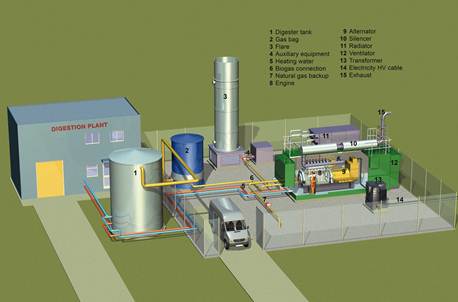
- Anaerobic digester tank: the anaerobic fermentation of the prepared bio-input.
- Gas bag: biogas produced in the anaerobic digester tank is collected in the flexible gas storage tank to ensure continuous supply of biogas, independent of fluctuations in the biogas production.
- Flare: for safety reasons, the installation of a gas flare is recommended so that excess gas can be released safely in the event of excessive gas production.
- Auxiliary equipment: switches the flare on/off in case the biogas quantity increases or drops, or when the CHP unit is switched off for example for annual maintenance or repair.
- Heating water: cold water is transferred from the anaerobic digestion plant and other buildings into the CHP unit. Here, the heat recovery system takes the 'waste heat' from the engine jacket and/or from the exhaust gas to heat up the water. This thermal energy can be used to heat the digester, to offset the heat requirements of the treatment plant or can be sold to local buildings.
- Biogas connection: the biogas is transferred from the gas bag into the CHP unit.
- Natural gas: as an option, natural gas can be connected to the system to provide additional electrical energy or heat if required (separate power unit).
- Engine: a range of 6 to 20 cylinder turbo charged reciprocating engines, in sizes from 165kW to 2MW are available for biogas applications. The engine is fully integrated with the anaerobic digestion plant and can be controlled and monitored from anywhere on the plant. It also features the ENER-G Gkontrol system for remote monitoring and fault diagnosis.
- Alternator: electric generator powered by the engine that produces alternating current.
- Silencer: reduces the engine's exhaust gas noise. The engine is hosted in a fully noise proof container, therefore the system can be applied in noise-sensitive locations.
- Radiator: cools the engine by transferring heat from the engine.
- Ventilator: helps avoid overheating of the engine by providing reduction in short-circuit air flow from the pressure side to the suction side of the ventilation radial fan.
- Transformer: transfers electrical energy from the alternator to the (HV) cable.
- Electricity HV cable: the electrical energy generated by the CHP unit can be utilised for the treatment plant as well as to supply the public power grid and sold as renewable electricity.
- Exhaust: the engine exhaust emissions are fully compliant with EU standards.
- Post-treatment of the residual digest material takes place and the end product from the fermentation of the biomass can be utilized as fertilizer.